Figura 8, Figura 9, Figura 8 y – Hypertherm Powermax125 Rev.1 Service manual Manual del usuario
Página 122: Figura 9 repre
Advertising
122
Powermax125 Manual de servicio 808073
8 – Localización de problemas y ensayos al sistema
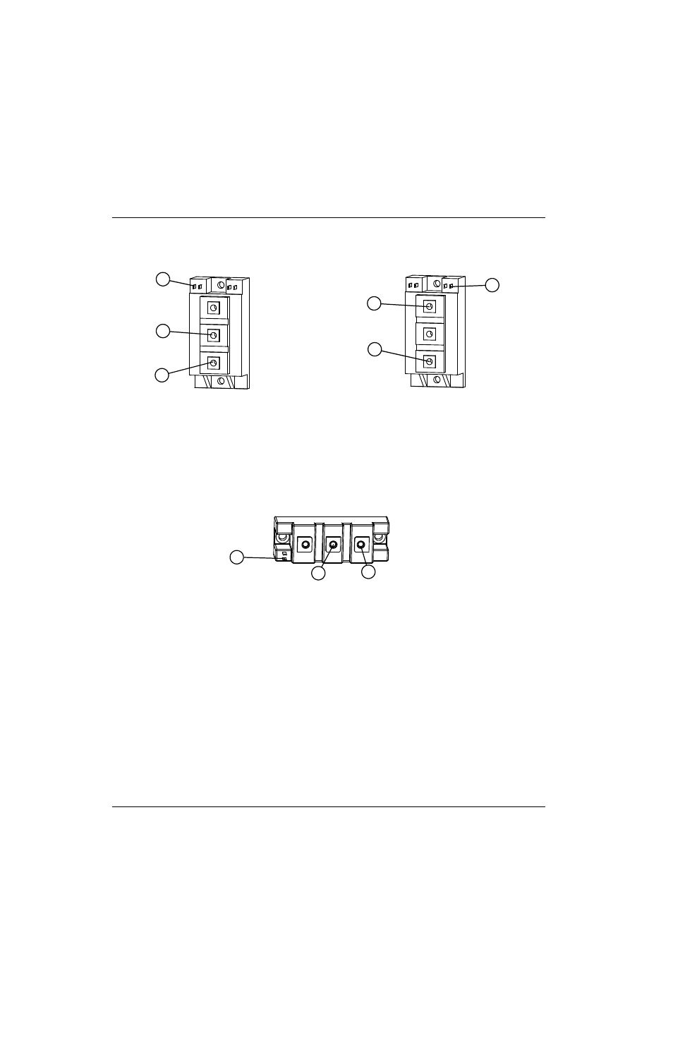
Figura 8 – Mediciones IGBT inversor
Figura 9 – IGBT, arco piloto
Prueba 1
Prueba 2
1
2
3
4
5
6
1
Punta amarilla compuerta (“G2” o “6”)
2
Punta negra emisor (“E2” o “2”)
3
Punta roja colector (“C2E1” o “1”)
4
Punta roja colector (“C1” o “3”)
5
Punta negra emisor (“C2E1” o “1”)
6
Punta amarilla compuerta (“G1” o “4”)
1
2
3
1
Punta amarilla compuerta 2 (“G2” o “6”)
2
Punta negra emisor 2 (“E2”o “2”)
3
Punta roja colector 2 (“C2” o “1”)
Advertising
Este manual se refiere a los siguientes productos: