Basler Electric DECS-400 Manual del usuario
Página 265
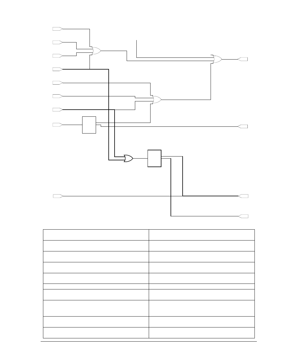
Figura A-15. Ilustración de modificación del esquema de lógica
Generator Overvoltage Active
(Input Buffer)
Sobretensión del generador activa
(Búfer de entrada)
Generator Undervoltage Active
(Input Buffer)
Subtensión del generador activa
(Búfer de entrada)
Loss of Field Active
(Input Buffer)
Pérdida de campo activa
(Búfer de entrada)
V/Hz Protection Active
(Input Buffer)
Protección V/Hz activa
(Búfer de entrada)
Layer 1
Gate 05
Capa 1
Compuerta 05
From Layer 1, Gate 04 Output
Desde salida de capa 1, compuerta 04
Layer 2
Gate 02
Capa 2
Compuerta 02
Relay Output #2
Common Protection
(Output Buffer)
Salida de relé n.º 2
Protección común
(Búfer de salida)
Field Overtemperature Active
(Input Buffer)
Sobretemperatura de campo activa
(Búfer de entrada)
Field Overvoltage Active
(Input Buffer)
Sobretensión de campo activa
(Búfer de entrada)
Relay Output #4
Loss of Sensing
(Output Buffer)
Generator Overvoltage
Active
(Input Buffer)
Layer 1
Gate 05
Generator Undervoltage
Active
(Input Buffer)
Loss of Field
Active
(Input Buffer)
V/Hz Protection
Active
(Input Buffer)
Field Overtemperature
Active
(Input Buffer)
Layer 1
Gate 06
Field Overvoltage
Active
(Input Buffer)
Field Overcurrent
Active
(Input Buffer)
u
2
u
3
u
4
u
1
x
1
MUX
u
4
u
4
Relay Output #2
Common Protection
(Output Buffer)
Layer 2
Gate 02
Layer 1
Gate 04
Loss of Sensing
Active
(Input Buffer)
P0043-20
09-12-06
From Layer 1,
Gate 04 Output
Build Up
Active
(Input Buffer)
Output Relay #5
(Output Buffer)
Output Relay #6
(Output Buffer)
+
+
+
Layer 3
Gate 01
u
2
u
3
u
4
u
1
x
1
MUX
u
4
u
4
Layer 4
Gate 01
9369772990 Rev R
Lógica programable del DECS-400
A-39