Basler Electric DECS-400 Manual del usuario
Página 246
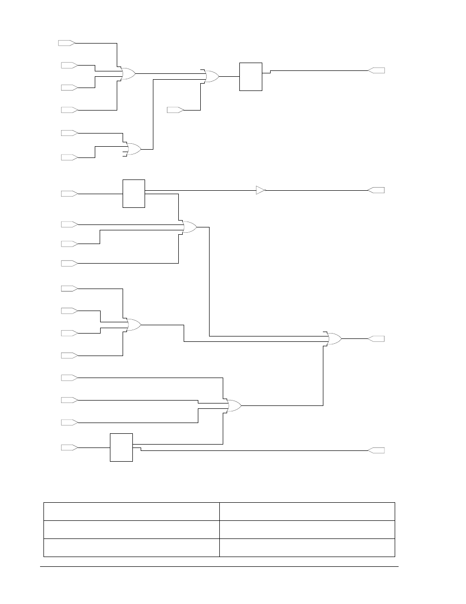
Figura A-8. DECS-400 simple sin PSS (Parte 3 de 3)
OEL Active
(Input Buffer)
OEL activo
(Búfer de entrada)
UEL Active
(Input Buffer)
UEL activo
(Búfer de entrada)
SCL Active
(Input Buffer)
SCL activo
(Búfer de entrada)
OEL Active
(Input Buffer)
Output Relay #3
Common Limiter(s)
(Output Buffer)
Transfer to FCR on
Loss of Sensing
Enable
(Output Buffer)
Relay Output #4
Loss of Sensing
(Output Buffer)
Layer 1
Gate 01
UEL Active
(Input Buffer)
SCL Active
(Input Buffer)
V/Hz Limiter Active
(Input Buffer)
Layer 1
Gate 02
Setpoint Adjustment
High Limit
(Input Buffer)
Setpoint Adjustment
Low Limit
(Input Buffer)
Under-Frequency
Active
(Input Buffer)
u
2
u
3
u
4
u
1
x
1
MUX
u
4
u
4
Generator Overvoltage
Active
(Input Buffer)
Layer 1
Gate 05
Generator Undervoltage
Active
(Input Buffer)
Loss of Field
Active
(Input Buffer)
V/Hz Protection
Active
(Input Buffer)
Loss of Isolation Module
Active
(Input Buffer)
Layer 1
Gate 04
Failed to Build Up
Active
(Input Buffer)
EDM Open Active
(Input Buffer)
EDM Shorted Active
(Input Buffer)
Field Overtemperature
Active
(Input Buffer)
Layer 1
Gate 06
Field Overvoltage
Active
(Input Buffer)
Field Overcurrent
Active
(Input Buffer)
u
2
u
3
u
4
u
1
x
1
MUX
u
4
u
4
Layer 1
Gate 04
u
2
u
3
u
4
u
1
x
1
MUX
u
4
u
4
Relay Output #2
Common Protection
(Output Buffer)
Layer 2
Gate 02
Layer 2
Gate 03
Layer 1
Gate 03
Layer 1
Gate 04
Layer 1
Gate 03
Loss of Sensing
Active
(Input Buffer)
P0036-10
02-01-06
A-20
Lógica programable del DECS-400
9369772990 Rev R