Basler Electric DECS-400 Manual del usuario
Página 230
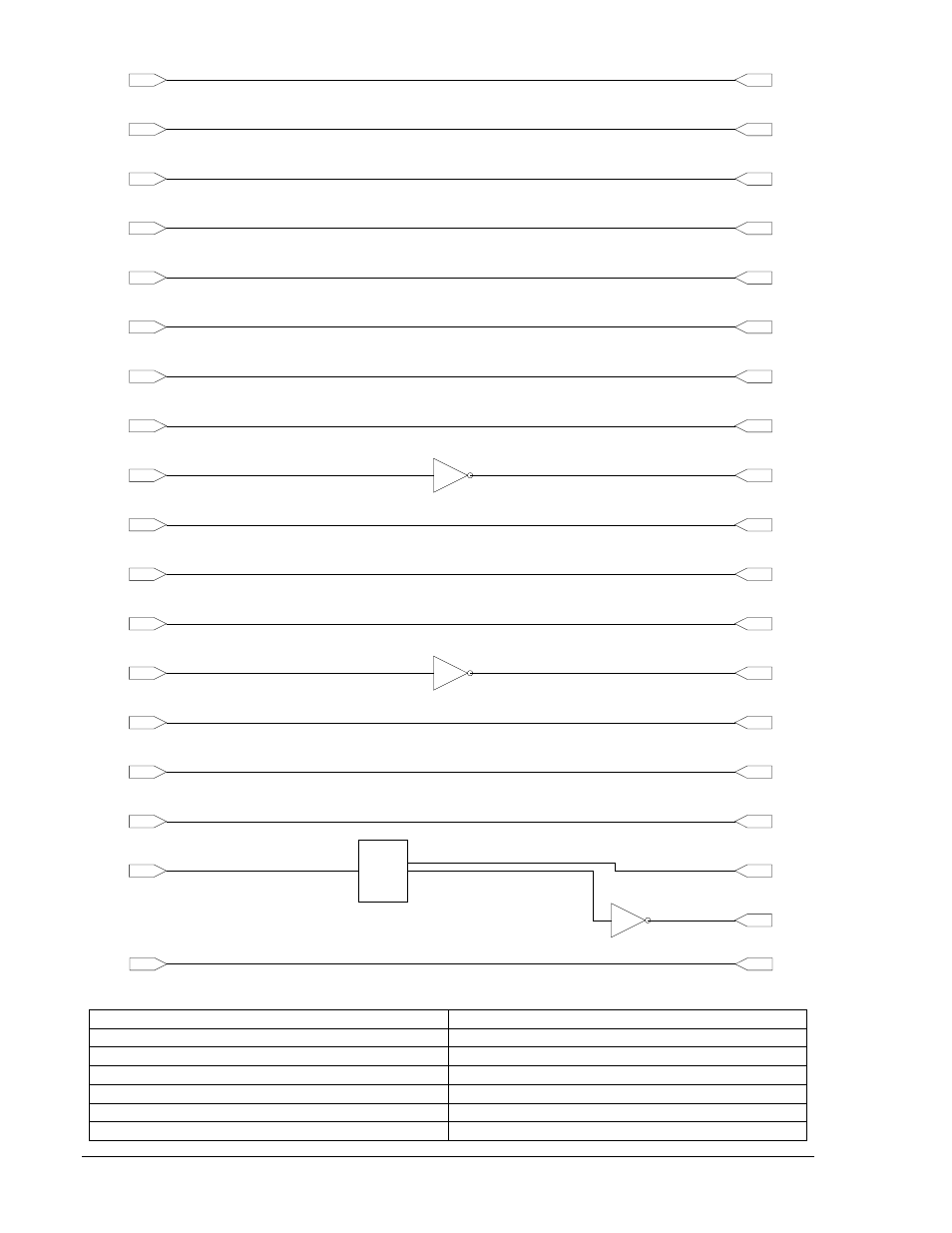
Figura A-2. Lógica predeterminada
Start Input
Entrada de arranque
Start Initiate
Iniciar arranque
Stop Input
Entrada de detención
Stop Initiate
Iniciar detención
AVR Input
Entrada AVR
AVR Initiate
Iniciar AVR
Manual Input
Entrada manual
Start Input
Stop Input
AVR Input
Manual Input
Raise Input
Lower Input
Switch Input 1
Alarm Reset
Switch Input 2
Pre-Position #2
Switch Input 3
52L/M
Switch Input 4
Secondary DECS Select
Switch Input 5
Pre-Position #1
Switch Input 6
Sec. Prot. Settings Select
Switch Input 7
52J/K
Switch Input 8
Secondary PID Select
Switch Input 9
PSS Enable
Switch Input 10
Sec. PSS Settings Select
Load Comp. Status
0=Off-Line, 1=On-Line
Start Initiate
Stop Initiate
AVR Initiate
Manual Initiate
Raise Setpoint Initiate
Lower Setpoint Initiate
Alarm Reset Initiate
Pre-Position #2 Initiate
Parallel Mode Activate
Auto-Transfer Enable
Pre-Position #1 Initiate
Secondary Protection
Settings Enable
Var/PF Mode Activate
Secondary PID Select
PSS Control Enable
Secondary PSS
Settings Select
OEL Option
0=Off-Line, 1=On-Line
Voltage Matching
0=Disabled, 1=Enabled
Layer 1, Gate 1
Layer 1, Gate 2
Layer 1, Gate 3
u
2
u
3
u
4
u
1
x
1
MUX
u
4
u
4
Layer 1, Gate 1
P0070-40
Fixed Logic
FALSE #10
Manual FCR Only
A-4
Lógica programable del DECS-400
9369772990 Rev R