Limitorque actuation systems, Flow control division, Compartimiento de control compartimiento del ly – Flowserve LY Series Quarter-Turn Electric Actuator Manual del usuario
Página 34: Limit switch contact development, Gr o c
6-6
Instalación y mantenimiento de la serie LY para LY 1001, LY 2001 y LY 3001
FCD LMLIM1501-00
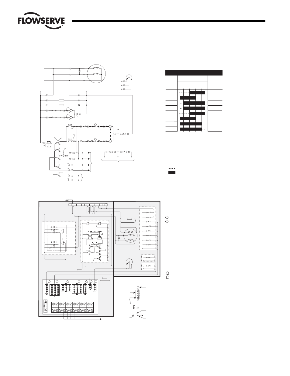
Figura 6.4 – Actuador monofásico con paquete de control
PIN NUMBER
CONNECTOR
NUMBER
CONNECTOR
T B 2 - 1 2
SYMBOL DESCRIPTION
TERMINAL
POINT
TERMINAL
STRIP
NUMBER
TERMINAL
POINT
NUMBER
1-4
1
2
3
4
TQ
SW
1
CONNECTOR
+
+
COMPARTIMIENTO DE CONTROL
COMPARTIMIENTO DEL LY
1
10
13
7
4
11
12
14
8
5
2
15
9
6
3
3
6
2
5
4
1
2
3
4
1
2
3
4
1
1
2
2
1
1
2
3
4
5
6
7
8
9
10
2
3
4
5
6
7
8
9
10
3
6
9
2
5
8
12
11
1
4
7
10
11
11
12
12
INTEGRAL P.C. BOARD
3
1
2
3
4
5
6
7
TQ
SW
GL
SW
INTG
CONT
SW
STAT
MTR HTR
TH.OL
COMP
HTR
POT
TB1
TB2
J1
9
8
7
1
HTR2
6-1
6-2
INCOMING POWER
L1
47
57
C
19
21
19
3-6
L1 L2
2C
3
3C
BROWN
PINK
GRAY
PURPLE
PURPLE
ORANGE
BRN
TO CUSTOMER'S
EQUIPMENT
T2
2
OPEN
CLOSE
TS17
1-1
1-2
TS18
1-4
1-3
2-10
2-7
GEAR LIMIT SWITCH
BOTTOM
LS9
2
2C
LS2
7-1
7-2
7-3
TORQUE SWITCH
TOP
POT
(OPTIONAL)
L2
3-8
(T3)
5-1 5-3 5-3 5-4
L1
57
47
O
21
19
PB1
OPEN
PB3
CLOSE
PB2
STOP
LOCAL
REMOTE
3-3
3-2
3-5
3-1
3-4
SW STATION
INTEGRAL CONTROL
SS
BLACK
BLUE
YELLOW
3-7
3-7
T1
2-2
2-12
2-1
2-13
2-15
2-11
2-14
2-8
2-5
2-4
LS7
LS4
LS8
LS5
LS6
3
3C
LS3
5-1
5-2
HTR1
5-2
RED
WHITE
WHITE
GREEN
R
G
MOTOR
T2
T1
TH.OL
CAP
3-9
3-9
5-4
5-3
L2
+
(P)
(P)
L1
TB2
-2
3-6
3-3
3-2
PB1
OPEN
PB2
STOP
3-5
3-4
TB2-7
(OPEN)
TB2-6
(CLOSE)
PB3
CLOSE
17
LOCAL
REMOTE
O
C
O
C
47
57
L2
21
L2
L1
L1
L2
O
C
C
O
L1
L2
18
TB2-8
TB2-5
(STOP)
TB2-4
(COMMON)
SS
3-1
HTR1
HTR2
L2
L2
TB2
-1
TB2-9
TB2-10
1-4
1-3
1-1
1-2
2-1
2-2
4-5
4-6
4-10
4-6
4-6
4-3
4-1
4-2
5-1
5-2
6-1
6-2
4-11
19
3-8
4-11
BLACK
BLUE
YELLOW
ORANGE
BROWN
PINK
GRAY
PURPLE
R
G
TB1-9
POT
(OPTIONAL)
7-1
7-2
7-3
TB1-10
TB1-8
L2
LS9
LS5
LS4
LS8
2-7
2-8
2-10
2-11
2-4
2-5
LS7
LS6
TB1-3
TB1-1
TB1-2
2-12
2-13
2-14
2-15
FOR REMOTE INDICATION
(WHEN REQUIRED)
FOR REMOTE INDICATION
(WHEN REQUIRED)
TO
CUSTOMER'S
EQUIPMENT
TB2
-11
TB2-12
4-8
4-9
RED
GREEN
4-7
WHITE
4-4
3-7
TH.OL
5-3
5-4
T2
T1
CAP.
L2 (T3)
MOTOR
L1
L2
L2
3-9
+
Limit Switch Contact Development
LIMIT
SWITCH
CONTACT
2
3
4
5
6
7
8
9
VALVE POSITION
FULL
OPEN
FULL
CLOSE
FUNCTION
SPARE
SPARE
OPEN LIMIT
IND LIGHT
INDICATION
INDICATION
CLOSED LIMIT
IND LIGHT
TS18 — Si se abre el switche de torque, se interrumpe el
circuito de control si tiene lugar una sobrecarga mecánica
durante el ciclo de apertura
TS17 — Si se cierra el switche de torque, se interrumpe el
circuito de control si tiene lugar una sobrecarga mecánica
durante el ciclo de cierre
NOTAS
1. Contacto abierto
2. Contacto cerrado
3. Todos los puntos de disparo del switche
de posición son totalmente ajustables
La válvula se muestra en posición totalmente abierta
G
R
O
C
LEYENDA
O — Abrir contacto
C — Contacto cerrado
— Bobina de apertura
— Bobina de cierre
CAP — Capacitor del motor
+ — Interbloqueo mecánico
TH. OL — Contactos de sobrecarga térmica
SS — Switche selector (local-remoto)
PB1 — Botón de apertura
PB2 — Botón de parada
PB3 — Botón de cierre
HTR1 — Calentador del entorno (compartimiento del LY)
HTR2 — Calentador del entorno (compartimiento de control)
POT — Transmisor del cable corredizo (opcional) Consulte
la hoja de certificación si se le entregó
J1 — Conector para Moductronic, 20 unidades
— Luz indicadora roja
— Luz indicadora verde
Nota: para el armado, consulte
los datos certificados
Flow Control Division
Limitorque Actuation Systems