Powermax, Diagramas eléctricos 8-2, Manual de servicio – Hypertherm Powermax45 Rev.2 Manual del usuario
Página 144: Control pwa
Diagramas eléctricos
8-2
powermax
45
Manual de servicio
FAULT
YEL
AMPS
CW
CAPOFF
YEL
"TSO/TSC"
AC PWR
GRN
"L/H LINE"
720
IN
15
IN
9
V-
8
IN
7
IN
13
IN
12
IN
11
IN
10
IN
6
V+
16
IN
3
IN
2
IN
1
IN
5
IN
14
IN
4
JTAG
1
3
5
7
9
11
13
14
2
4
6
8
10
12
1 2
3 4
5 6
7 8
9 10
11 12
13 14
15 16
17 18
19 20
21 22
23 24
25 26
2
1
3
4 56
7
ON
ON CASE
CASE
1
2
3
4
TEMP
YEL
L
R
1
ERROR
CODE
.25"
FOR
BD
DEPAN-
IZATION
SERIAL
DATA
MACHINE
FRONT
DSP 2806
4x25Mhz=100Mhz
0.78 x 0.78"
Stayout for
TEST CLIP
/RESET or
HDR FLT
START
XFR
GAS
CONTROL PWA
CPA (UP)
NORMAL (MIDDLE)
GOUGE (DOWN)
YEL
YEL
GRN
"SETPOINT"
GRN
GRN
MODE
45 A 230 V
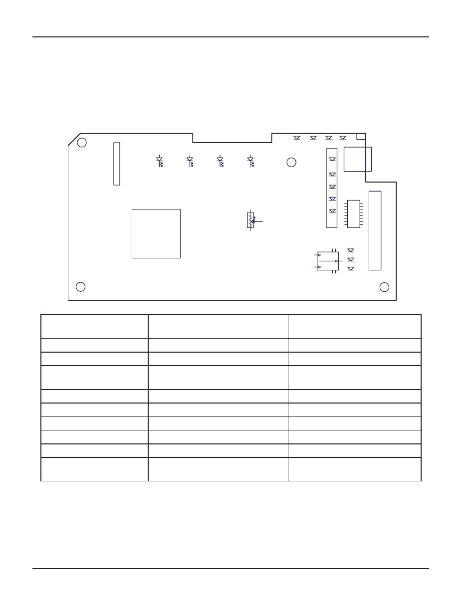
Esquema tarjeta de control: CSA 200-240 V y CE 230 V
Número pin j7 a tierra
Prueba
Valor previsto
(CSA 200-240 V o CE 230 V)
19
VCAR (voltaje de línea CA rectificado)
1,95 V a voltaje de línea 230
21
VBUS (voltaje de bus CC)
2,28 VCD a VBUS 385
18
(solo 200-240 y 230 V)
IPFC (corriente de entrada)
< 0,1 VCD
20
IFB (corriente de salida)
< 0,1 VCD
22
ITF (corriente transferencia)
< 0,1 VCD
25
3,3 VCD
3,3 VCD ±5%
24
5 VCD
5 VCD ±5%
12
Pin sensado 24 V
2,2 VCD
16
Señal arranque
3,2 VCD cerrado
0 VCD abierto