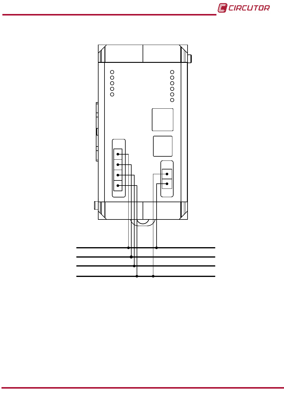
4�1�4� esquema de conexionado, L1 l2 l3 n, Manual de instrucciones sistema cirlamp – CIRCUTOR CIRLAMP Series Manual del usuario
Página 13
Advertising
Ver también otros documentos de la categoría Instrumentos de medición CIRCUTOR:
- CVMk2 Series (Páginas: 152)
- QNA500 series (Páginas: 113)
- CVM-C5 Series (Páginas: 40)
- CVM-C10 Series (Páginas: 82)
- CVM-MINI Series (Páginas: 26)
- CVM-NET Series (Páginas: 2)
- CVM-1D Series (Páginas: 2)
- CVM-BDM Series (Páginas: 32)
- PowerNet Series (Páginas: 3)
- CVM-NRG96 Series (Available until stocks) (Páginas: 38)
- CVM-B Series (Páginas: 320)
- CVM96 Series (Páginas: 44)
- CVM144 Series (Páginas: 58)
- TCP1RS+ (Páginas: 2)
- EDS-3G Series (Páginas: 6)
- CMBUS series (Páginas: 24)
- MDC-4 (Páginas: 30)
- LM50-TCP+ (Páginas: 2)
- MDC-20 (Páginas: 58)
- Modem GSM Series (Páginas: 2)
- ReadWatt Series (Páginas: 22)
- PowerStudio Series (Páginas: 42)
- PowerStudio Series (Páginas: 110)
- PowerStudio Series (Páginas: 110)
- PowerStudio Series (Páginas: 296)
- OPC Server PS/PSS (Páginas: 22)
- PowerWatt Series (Páginas: 123)
- AR6 Series (Páginas: 69)
- AR5L Series (Páginas: 52)
- CIRe3 Series (Páginas: 50)
- CIReQ (Páginas: 36)
- C80 Series (Páginas: 25)
- QNA-P Series (Páginas: 36)
- T3V Series (Páginas: 8)
- CPM (Available until stocks) (Páginas: 19)
- CDB (Available until stocks) (Páginas: 35)
- DHB Series (Páginas: 80)
- DHB Series (Páginas: 68)
- EMF-EMB Series (Páginas: 11)
- CIRWATT-B505 Series (Páginas: 52)
- CEM-C10 series (Páginas: 36)
- CEM-C30 series (Páginas: 42)
- CEM-M-RS-485 (Páginas: 26)
- CEM-M-ETH (Páginas: 24)