3 entradas jack, Fig 5.5 fig 5.6, Fig 5.4 – BSS Audio FCS-966 Owner's Manual Manual del usuario
Página 11
11
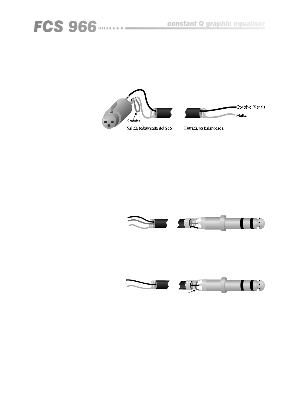
When using the FCS 966 to drive unbalanced inputs, best performance is
usually obtained by connecting the FCS 966s ‘+’ signal to the equipment signal
pin and the ‘-’ signal to the equipment shield.
The FCS 966 shield should normally be connected to the equipment shield,
preferably at the equipment end. Transformer isolated outputs are also
available as a dealer fitted option.
Entrada jack del 966
Salida balanceada
Masa
Positivo '+'
Negativo '-'
Carcasa
Extremo : Positivo '+'
Anillo: Negativo '-'
C
E
A
ColdNegativo '-'
Positivo '+'
Malla
A
E
C
5.3 Entradas Jack
The jack inputs are electrically identical to the XLR inputs. The ‘HOT, +, or in
phase’ connection is to the jack plug tip, the ‘COLD, - or out of phase’
connection to the ring. The shield is internally connected to the chassis earth
via a low value capacitor. This ensures freedom from ground loops whilst
allowing good EMC performance. The screen of the cable must be connected
to the jack plug shield to ensure continued compliance with EMC regulations.
The cable shield ground should be connected to the equipment which is
providing the input signal.
Fig 5.5
Fig 5.6
Salida no balanceada
Positivo (Senal)
Malla
Entrada jack del 966
C
E
A
Union
C
A
E
When feeding the FCS 966 from unbalanced sources, connect the signal
conductor to the jack plug tip and the cable screen to the plug ring and shield.
Fig 5.4